Description
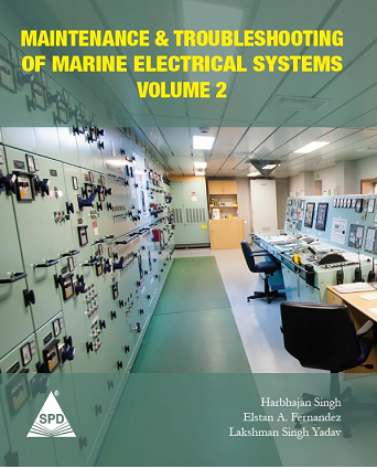
This book is a sequel to the book titled Maintenance and Troubleshooting of Marine Electrical Systems. The book is written in 8 chapters by Lakshman Singh Yadav and Elstan A. Fernandez, and focuses on the Guidelines for the Troubleshooting and Maintenance of both Low and High Voltage Systems in general and also the Troubleshooting of Generators, Motors and the Distribution System.
This book written in 38 Chapters, focuses on a wide range of systems / equipment installed on the Bridge, the Deck and in the Engine Room. It contains authentic information and guidelines that will help any Engineer at sea to quickly address both common and intricate issues.
Furthermore, as a “First” for the Maritime Industry, the entire series of books depicted on the inside of this cover will be available in E-Book formats too. In addition, the authors are always open to offering guidance and help for those engineers who find it a challenge to identify and rectify faults on board commercial ships.
Contents
| Chapter No. | Title | Page No. |
| 1 | Electrical Safety | 1 |
| 2 | Introduction to Alarm and Monitoring Systems | 39 |
| 3 | MSBs, ACB, GSP | 45 |
| 4 | Integrated Monitoring and Control System | 59 |
| 5 | Main Engine Alarm and Safety System | 87 |
| 6 | M.E. Engine Alarms Handling and References | 103 |
| 7 | Electronic Governor | 181 |
| 8 | Main Engine Exhaust Gas Scrubber System | 213 |
| 9 | Air Compressors | 219 |
| 10 | Oil Purifiers | 227 |
| 11 | Viscosity Controller | 235 |
| 12 | Fresh Water Generator | 241 |
| 13 | Boilers | 249 |
| 14 | Inert Gas System | 269 |
| 15 | Oily Water Separators | 279 |
| 16 | Incinerators | 301 |
| 17 | Sewage Treatment Plants | 321 |
| 18 | Heaters and Coolers | 335 |
| 19 | Air Conditioning System | 345 |
| 20 | Axial Flow Fan | 349 |
| 21 | Magnetic and Gyro Compasses | 351 |
| 22 | Global Positioning System | 369 |
| 23 | ECDIS | 375 |
| 24 | Echo Sounder and Electro Magnetic Log | 381 |
| 25 | Anemometer and Anemoscope | 385 |
| 26 | BNWAS and Master Clock | 387 |
| 27 | VHF Communication Set | 389 |
| 28 | Weather Facsimile | 393 |
| 29 | Steering Systems | 395 |
| 30 | Deck Machinery | 425 |
| 31 | Ejectors and Pumps | 441 |
| 32 | Oil Discharge Monitoring and Control System | 453 |
| 33 | Tank Radar | 471 |
| 34 | Gas Detection System | 489 |
| 35 | Fire Detection Systems | 503 |
| 36 | Internal Communication Systems | 533 |
| 37 | Lifeboats | 551 |
| 38 | Maintenance and Troubleshooting of Hydraulics | 561 |
| Chapter 1 – Electrical Safety | ||
| Article No. | Article | Page No. |
| 1.1 | Compliance with Regulations | 1 |
| 1.2 | The Inherent Dangers and Avoidance of Disastrous Consequences | 6 |
| 1.3 | Passive Safety Measures | 8 |
| 1.4 | Active Safety Measures | 12 |
| 1.5 | Fundamental Requirements for Safe Installation of Equipment | 15 |
| 1.6 | Dos and Don’ts While Working with Electrical Equipment | 16 |
| 1.7 | Danger Signals | 20 |
| 1.8 | Precautions for Preventing an Electric Shock | 20 |
| 1.9 | Conditions which Increase Danger to Personnel | 22 |
| 1.10 | Shock Risk with Portable AC Appliances | 23 |
| 1.11 | High Voltage Safety | 27 |
| 1.12 | Electrical Accidents | 31 |
| 1.13 | Maintenance of Records | 38 |
| Chapter 2 – Introduction to Alarm and Monitoring Systems | ||
| Article No. | Article | Page No. |
| 2.1 | Alarm and Monitoring Systems | 39 |
| 2.2 | Alarm Scanning | 41 |
| Chapter 3 – MSBs, ACB, GSP | ||
| Article No. | Article | Page No. |
| 3.1 | Main Switch Board PLC Omron 200H Troubleshooting | 45 |
| 3.2 | Air Circuit Breakers | 49 |
| Chapter 4 – Integrated Monitoring and Control System | ||
| Article No. | Article | Page No. |
| 4.1 | A Typical Example of Main Machinery Control Onboard a Container UMS Ship | 59 |
| 4.2 | Integrated Monitoring and Control System (IMCS) | 59 |
| Chapter 5 – Main Engine Alarm and Safety System | ||
| Article No. | Article | Page No. |
| 5.1 | General Description | 87 |
| 5.2 | Engine Safety Unit (ESU) | 88 |
| 5.3 | Engine Limiters | 93 |
| 5.4 | Safety System Operation | 95 |
| 5.5 | Alarm Inputs and History | 97 |
| 5.6 | Testing “Shut Down” When the Main Engine (M/E) is Stopped | 98 |
| 5.7 | Oil Mist Detector MD 9M | 101 |
| Chapter 6 – M.E. Engine Alarms Handling and References | ||
| Article No. | Article | Page No. |
| 6.1 | Alarm Handling on the Main Operating Panel – HMI (Human Machine Interface) | 103 |
| 6.2 | Alarms Reference | 108 |
| Chapter 7 – Electronic Governor | ||
| Article No. | Article | Page No. |
| 7.1 | Quick Reference Table for Failures | 181 |
| 7.2 | GOV. FAIL “MICRO – PROCESSOR” LED is On | 184 |
| 7.3 | GOV. FAIL “REV. DETECT UNIT” LED is On | 184 |
| 7.4 | Lighting of GOV. FAIL “RPM SENSOR” | 185 |
| 7.5 | Lighting of GOV. FAIL “SCAV AIR SENSOR” | 186 |
| 7.6 | Lighting of GOV. FAIL “ACTUATOR UNIT” | 186 |
| 7.7 | GOV. POWER FAIL | 192 |
| 7.8 | EMS SYSTEM FAIL (During C / F Control) | 193 |
| 7.9 | ECS SYSTEM FAIL (During the W/H Control) | 194 |
| 7.10 | Indication of Several Alarms | 197 |
| 7.11 | Remedies for Alarms – Number Wise | 198 |
| 7.12 | Mitsui MAN B&W | 205 |
| 7.13 | Running Difficulties | 209 |
| Chapter 8 – Main Engine Exhaust Gas Scrubber System | ||
| Article No. | Article | Page No. |
| 8.1 | Main Engine Exhaust Gas Scrubber System | 213 |
| 8.2 | Moisture Alarms | 214 |
| 8.3 | Feen Marine Scrubbers Inc. Corrective Actions Table | 216 |
| Chapter 9 – Air Compressors | ||
| Article No. | Article | Page No. |
| 9.1 | Main Air Compressor (Tanabe) | 219 |
| 9.2 | Main Air Compressor (Dong Hwa Pneutec) | 221 |
| 9.3 | Main Air Compressor (MAC Saucer WP15L) | 224 |
| Chapter 10 – Oil Purifiers | ||
| Article No. | Article | Page No. |
| 10.1 | Fuel Oil Purifiers (Mitsubishi SJ 40 FH) | 227 |
| 10.2 | Alfa Laval Purifiers | 230 |
| 10.3 | EPC Controls | 231 |
| Chapter 11 – Viscosity Controller | ||
| Article No. | Article | Page No. |
| 11.1 | Control Valves | 235 |
| 11.2 | Flow Meter Failure | 236 |
| 11.3 | General Troubleshooting | 238 |
| 11.4 | Temperature Troubleshooting | 239 |
| 11.5 | Process Troubleshooting | 239 |
| 11.6 | The Viscosity Signal is Too Low | 240 |
| 11.7 | The Viscosity Signal Remains at the Maximum Value | 240 |
| 11.8 | No Viscosity Signal | 240 |
| 11.9 | No Temperature Signal | 240 |
| Chapter 12 – Fresh Water Generators | ||
| Article No. | Article | Page No. |
| 12.1 | Fresh Water Generator – Make: DongHwa | 241 |
| 12.2 | Sasukara Fresh Water Generator Tubular Type | 245 |
| Chapter 13 – Boilers | ||
| Article No. | Article | Page No. |
| 13.1 | Oilon Boiler Burner | 249 |
| 13.2 | Watching the Boiler Room (if there is one) | 250 |
| 13.3 | Symptoms and Probable Causes in General | 251 |
| 13.4 | Generic Guidelines | 255 |
| 13.5 | Specific Guidelines – Mitsubishi MAC-25B | 258 |
| 13.6 | ALBORG OL 25000 kg/h | 263 |
| 13.7 | HZAM – 39T | 267 |
| Chapter 14 – Inert Gas System | ||
| Article No. | Article | Page No. |
| 14.1 | Inert Gas System (MISUZU-FMV) | 269 |
| Chapter 15 – Oily Water Separators | ||
| Article No. | Article | Page No. |
| 15.1 | Oily Bilge Water Separator HMS-200 | 279 |
| 15.2 | Oily Water Separator Model GRS – 100EB | 282 |
| 15.3 | Oily Water Separator Model USC – 20 | 285 |
| 15.4 | Oily Water Separator Model USH – 50 FOCUS – 1800 | 288 |
| 15.5 | Oily Water Separator Type HFM – 1 | 292 |
| 15.6 | Oily Water Separator SMT- 10A | 296 |
| Chapter 16 – Incinerators | ||
| Article No. | Article | Page No. |
| 16.1 | Incinerator Type – VIRM – 70 | 301 |
| 16.2 | Incinerator Volcano VIM – 50 | 302 |
| 16.3 | Waste Oil Incinerator Type: MAXI T50/T100/T150SL WS | 304 |
| 16.4 | Waste Oil Incinerator Model MIURA BGW-50 | 313 |
| 16.5 | The Auxiliary Burner System | 314 |
| 16.6 | The Waste Oil Burner System | 314 |
| 16.7 | The Combustion System (Auxiliary Burner System) | 315 |
| 16.8 | The Combustion System (Waste Oil Burner System) | 316 |
| 16.9 | The Safety Control and Alarm Circuit | 318 |
| 16.10 | The Waste Oil Incinerator Model OSV-30SA | 319 |
| Chapter 17 – Sewage Treatment Plants | ||
| Article No. | Article | Page No. |
| 17.1 | Sewage Treatment Unit ISB – 03 | 321 |
| 17.2 | Sewage Treatment Unit ISS – 60N | 326 |
| 17.3 | Chemical Pump (Fixed Quantity Pump) | 327 |
| 17.4 | Sewage Treatment Unit SBT – 40 | 330 |
| 17.5 | Sewage Treatment Unit SD – 3AN | 332 |
| 17.6 | Vacuum Toilet EVAC 90 | 333 |
| Chapter 18 – Heaters and Coolers | ||
| Article No. | Article | Page No. |
| 18.1 | APV Plate Heat Exchanger | 335 |
| 18.2 | Calorifier – Steam Heater | 336 |
| 18.3 | Vacuum Condenser | 337 |
| 18.4 | Tube Type Coolers | 340 |
| 18.5 | U-Type Oil Heater | 341 |
| 18.6 | Plate Type Heat Exchanger | 341 |
| Chapter 19 – Air Conditioning System | ||
| Article No. | Article | Page No. |
| 19.1 | Generic Issues | 345 |
| Chapter 20 – Axial Flow Fan | ||
| Article No. | Article | Page No. |
| 20.1 | In Case It Is Not Running | 349 |
| 20.2 | In Case It Is Running | 350 |
| Chapter 21 – Magnetic and Gyro Compasses | ||
| Article No. | Article | Page No. |
| 21.1 | Magnetic Compass (SH-165A2 SERIES) | 351 |
| 21.2 | Gyro Compass TG-8000 -8500 | 351 |
| 21.3 | Failure Phenomena and Countermeasures | 353 |
| 21.4 | Power Supply Abnormality (Alarm Code “1”) | 354 |
| 21.5 | Power Supply Abnormality (Alarm Code “2”) | 359 |
| 21.6 | Inverter Abnormality (Alarm Code “3”) | 359 |
| 21.7 | Rotor Level Abnormality (Alarm Code “6”) | 360 |
| 21.8 | Zero Cross Abnormality (Alarm Code “8”) | 360 |
| 21.9 | System Communication Abnormality (1) (Alarm Code “A”) | 360 |
| 21.10 | System Communication Abnormality (2) (Alarm Code “B”) | 362 |
| 21.11 | GPS Communication Stop (Alarm Code “C”)
Or Abnormality of GPS Data (Alarm Code “D”) |
364 |
| 21.12 | System Internal Communication Abnormality (1) (Alarm Code “E”)
Or System Internal Communication Abnormality (2) (Alarm Code “F”) |
364 |
| 21.13 | Master Compass Heading Abnormality (Alarm Code “G”) | 364 |
| 21.14 | External Heading Sensor Communication Stop (Alarm Code “L”)
Or External Heading Sensor Data Abnormality (Alarm Code “N”) |
365 |
| 21.15 | LOG (Serial Signal) Communication Stop (Alarm Code “P”)
Or LOG (Serial Signal) Data Abnormality (Alarm Code “U”) |
365 |
| 21.16 | LOG Contact Abnormality (Alarm Code “U”) | 365 |
| 21.17 | E5V Abnormality (Alarm Code “R”) | 366 |
| 21.18 | The Gyro-Compass Does Not Operate, When Power Switch On The Operating Panel Is Turned “ON”. | 366 |
| 21.19 | Each repeater does not operate. | 367 |
| 21.20 | All Repeaters Do Not Operate. | 368 |
| Chapter 22 – Global Positioning System | ||
| Article No. | Article | Page No. |
| 22.1 | Generic Guidelines | 369 |
| 22.2 | GPS JMR 7500 | 373 |
| Chapter 23 – ECDIS | ||
| Article No. | Article | Page No. |
| 23.1 | Generic Guidelines | 375 |
| Chapter 24 – Echo Sounder and Electro Magnetic Log | ||
| Article No. | Article | Page No. |
| 24.1 | Echo Sounder | 381 |
| 24.2 | Electro Magnetic Log | 383 |
| Chapter 25 – Anemometer and Anemoscope | ||
| Article No. | Article | Page No. |
| 25.1 | Generic Guidelines | 385 |
| Chapter 26 – BNWAS and Master Clock | ||
| Article No. | Article | Page No. |
| 26.1 | BNWAS JCX-161 | 387 |
| 26.2 | Master Clock System | 387 |
| Chapter 27 – VHF Communication Set | ||
| Article No. | Article | Page No. |
| 27.1 | VHF JHS-780 | 389 |
| 27.2 | Procedures for Locating Malfunctions | 389 |
| Chapter 28 – Weather Facsimile | ||
| Article No. | Article | Page No. |
| 28.1 | Weather Facsimile JAX-9B | 393 |
| Chapter 29 – Steering Systems | ||
| Article No. | Article | Page No. |
| 29.1 | Flutek-Kawasaki FE 21 – 288 – T050 | 395 |
| 29.2 | Single Loop Fork Type F-172 SG sys 1 | 402 |
| 29.3 | Steering Gear Mitsubishi type DF-250 | 403 |
| 29.4 | Autopilot | 406 |
| 29.5 | Rudder Angle Indicator | 422 |
| Chapter 30 – Deck Machinery | ||
| Article No. | Article | Page No. |
| 30.1 | Kawasaki | 425 |
| 30.2 | Maritime Pusnes AS | 426 |
| 30.3 | Nippon Pusnes | 436 |
| 30.4 | Hydraulic Parts | 437 |
| 30.5 | De-Aeration Method for The System | 439 |
| 30.6 | Hose Handling Crane | 439 |
| Chapter 31 – Ejectors and Pumps | ||
| Article No. | Article | Page No. |
| 31.1 | Attached Air Ejector | 441 |
| 31.2 | Attached Vacuum Pump | 442 |
| 31.3 | Centrifugal Pumps | 443 |
| 31.4 | Screw Pumps | 446 |
| 31.5 | Inside Bearing Pumps | 450 |
| Chapter 32 – Oil Discharge Monitoring and Control System | ||
| Article No. | Article | Page No. |
| 32.1 | ODME Clean track – 1000 | 453 |
| Chapter 33 – Tank Radar | ||
| Article No. | Article | Page No. |
| 33.1 | Abbreviations Used | 471 |
| 33.2 | System Failure Message: Level Unit System Fail | 471 |
| 33.3 | System Failure Message: Level Unit Communication Failed | 472 |
| 33.4 | System Failure message: Level Unit Power Failure | 472 |
| 33.5 | System Failure message: Level Unit LI Communication Failed | 472 |
| 33.6 | System Failure message: 1/0 Box Communication Failed | 473 |
| 33.7 | Warning Message: Level Unit Ground Failure | 473 |
| 33.8 | Warning Message: Level Unit Memory Failure | 473 |
| 33.9 | Warning Message: The Level Unit Restarted | 473 |
| 33.10 | Warning Message: Master Communication Failed | 474 |
| 33.11 | Warning Message: LevelDatic Communication Has Failed | 474 |
| 33.12 | Channels with Status CFAIL, ERROR or INVAL | 475 |
| 33.13 | CFAIL Status on Five Transmitters | 475 |
| 33.14 | ERROR Status on One Transmitter, But There is No CFAIL Status | 476 |
| 33.15 | Warning “Clean Antenna on Tank XXX” | 476 |
| 33.16 | All Warnings Associated with One Tank are Shown on the Work Station | 476 |
| 33.17 | There is an ERROR Status on One Temperature Sensor | 476 |
| 33.18 | INVAL Status on the Average Temperature | 477 |
| 33.19 | Work Station | 477 |
| 33.20 | Level Unit | 478 |
| 33.21 | Transmitters | 479 |
| 33.22 | Local Display | 479 |
| 33.23 | Temperature Measurement | 480 |
| 33.24 | Inert Gas Pressure Measurement | 480 |
| 33.25 | Tank Display Unit | 481 |
| 33.26 | Portable Readout System | 481 |
| 33.27 | Draft Measurement | 482 |
| 33.28 | Load Calculator | 483 |
| 33.29 | Finding the Probable Causes of Ground Failure Warnings | 483 |
| 33.30 | Valve Remote Control System | 486 |
| Chapter 34 – Gas Detection Systems | ||
| Article No. | Article | Page No. |
| 34.1 | Actions for Each Problem | 489 |
| 34.2 | Gas Sampling System Concellium | 493 |
| 34.3 | Gas Detecting System Komyo Rikagaku | 498 |
| 34.4 | Salwico Gas Detection System | 503 |
| Chapter 35 – Fire Detection Systems | ||
| Article No. | Article | Page No. |
| 35.1 | Fault Code List | 509 |
| 35.2 | Nippon Hakuyo Fire Detection System | 532 |
| Chapter 36 – Internal Communication Systems | ||
| Article No. | Article | Page No. |
| 36.1 | Auto Telephone Exchange System | 533 |
| 36.2 | Communal Aerial System | 535 |
| 36.3 | Master Clock System | 537 |
| 36.4 | Sound Power Telephone LC 800 | 539 |
| 36.5 | Intrinsically Safe Type of Common Battery Phone / Marine Automatic Telephone | 541 |
| 36.6 | Public Address System MPA 2000C | 542 |
| 36.7 | Public Address System | 548 |
| Chapter 37 – Lifeboats | ||
| Article No. | Article | Page No. |
| 37.1 | Difficulty in Starting the Engine | 551 |
| 37.2 | Insufficient Output | 551 |
| 37.3 | Black Smoke Coming from the Exhaust | 551 |
| 37.4 | Low Lubricating Oil Pressure | 552 |
| 37.5 | The Engine is Knocking | 552 |
| 37.6 | The Engine is Overheating | 552 |
| 37.7 | Engine Over Speed | 553 |
| 37.8 | Lifeboat Model BH7B | 553 |
| 37.9 | Lifeboat Model G63AFR | 555 |
| 37.10 | Lifeboat Model SZ 65 TRS | 556 |
| 37.11 | Lifeboat Model HDL 75 CF | 557 |
| Chapter 38 – Maintenance and Troubleshooting of Hydraulics | ||
| Article No. | Article | Page No. |
| 38.1 | Hydraulic Fluid Care | 561 |
| 38.2 | Fluid Change-Out Recommendations | 564 |
| 38.3 | Troubleshooting Guide | 567 |

